IAN T COBB
The Case
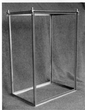
The Case with side and top glazing
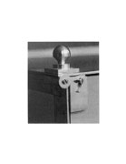
Details of one of the hooks for securing the front and back case panels and the decorative features on each corner
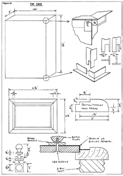
The case frame is made from 1/2” ‘T’ section brass to the overall dimensions shown on Figure 24.
Before cutting the mitres, it is advisable to clean up all faces of the ‘T’ section. It is surprising how much work needs to be done with file and abrasive paper to get rid of the surface imperfections.
The top and bottom rectangular frames are mitred at the corners. 1 used a jig on the lathe topside and a slitting saw to cut the 45 degree angles accurately. Also, by using a length stop for the second cut on each piece, the lengths were accurately cut. While the jig was mounted on the cross slide, I used it to cut the vertical bars across at right angles and with the stop in use for the second cut, the lengths were standardised.
The mitred joints on the top and bottom frames were silver soldered together using suitable clamps and weights to ensure squareness and flatness.
The two tongues formed by cutting away part of the 'T' section at the ends of the four vertical members were next cut and tidied up with a file. Each corner joint was marked with a letter (for identification) and the slots in the top and bottom frames were cut and finished to give a good fit at each corner. After cleaning up and fluxing, these joints are soft soldered making sure that the frame is square.
Two 1/8” X 1/16” brass strips are now cut to a good fit to the front and back bottom outer flanges. These act as retainers for the bottom of the removable front and back glasses. They are stuck in place with Loctite Super Glue Gel or could be soft soldered.
The tedious job of cleaning up and polishing the brass must now be tackled. When you are satisfied with the finish it can be given a coat of clear lacquer.
The four decorative features on the top corners (see photograph) are turned from 3/8” brass bar and the bases from 3/32” plate. They are stuck in place with Araldite Rapid Adhesive.
The top, sides and front are glazed with 2mm picture glass and the back is a sheet of 2mm thick mirror. The side and top panels are held in place with Translucent Evostick Bath, Sink and Shower Silicone Sealant. The top panel is fitted first and then the sides. Do not forget to allow for the thickness of the top panel when working out the sizes for the side panels.
The front and back panels are removable. They are retained in place at the top by small, 1/16” thick, brass
42
hooks as shown on Figure 24 and the photograph. Four 3/4” lengths of 3/16” square brass bar are centred, drilled and tapped 10 BA r the hook pivot screws and four 1/16” X 7/16” X 11/16” pads with 10 BA C/H screws form the lugs for the hooks on the removable panels. They are held in place with Araldite Rapid Adhesive.
The glazed cover fits on to a wood base. It consists of a profiled, stained and polished outer frame and a slightly raised and material covered central insert to which the clock is fixed. Figure 24 gives the dimensions for the section of the wooden surround, which is mitred at the corners. The central insert can be made from 3/8” thick MDF which should be cut to a loose fit in the outer wooden frame to allow for the thickness of the covering material which is stuck on the top and edges. 'Venelia' is a suitable material for this purpose. It is made in France and can be obtained in a range of colours to contrast with the brass and to match existing room furnishings. It is also self-adhesive and easy to apply. Other materials may be used. The covered insert panel can be glued and/or screwed to the outer wooden frame or left removable with some suitable means of retaining it in the outer frame. Three bun feet are turned and stuck/screwed to the outer wooden frame, two at the front and one at the back. The housing in the wooden frame is also covered with material to act as a cushion for the brass base of the cover. It is stuck in place with the inner edge over lapping the covered central panel and the outer edge butting up to the outer edge of the housing. Strips of the material are also stuck round the openings for the glass front and rear panels and a narrow (c. 1/8” wide) strip is stuck along the bottom of each removable panel and lapping up on the outer edge to act as a
cushion against the brass retaining strips.
The clock frame rests on two polished brass bearers (6” x 1” X 3/16”) and the base is firmly fixed to the bottom clock pillars with 4 BA C/S screws.